Sweeps the shaft of a RC servo motor back and forth across 180 degrees.
This example makes use of the Arduino servo library.
Hardware Required
- Arduino or Genuino Board
- Servo Motor
- hook-up wires
- Arduino or Genuino Board
- Servo Motor
- hook-up wires
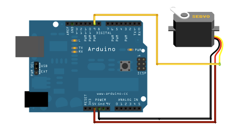
Circuit
Servo motors have three wires: power, ground, and signal. The power wire is typically red, and should be connected to the 5V pin on the Arduino or Genuino board. The ground wire is typically black or brown and should be connected to a ground pin on the board. The signal pin is typically yellow, orange or white and should be connected to pin 9 on the board.

Servo motors have three wires: power, ground, and signal. The power wire is typically red, and should be connected to the 5V pin on the Arduino or Genuino board. The ground wire is typically black or brown and should be connected to a ground pin on the board. The signal pin is typically yellow, orange or white and should be connected to pin 9 on the board.
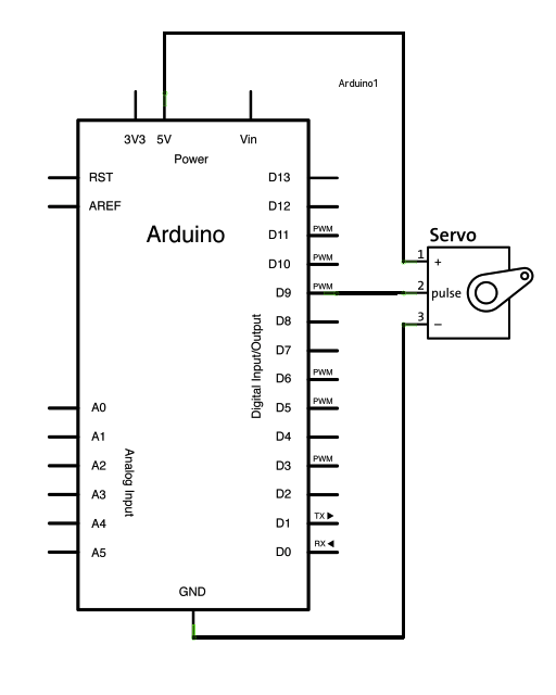
Schematic
CODE
#include <Servo.h>
Servo myservo;
int pos = 0;
void setup()
{
myservo.attach(9);
}
void loop()
{
for (pos = 0; pos <= 180; pos += 1)
{ myservo.write(pos); delay(15); }
for (pos = 180; pos >= 0; pos -= 1)
{ myservo.write(pos); delay(15); }
}
CODE
#include <Servo.h>
Servo myservo;
int pos = 0;
void setup()
{
myservo.attach(9);
}
void loop()
{
for (pos = 0; pos <= 180; pos += 1)
{ myservo.write(pos); delay(15); }
for (pos = 180; pos >= 0; pos -= 1)
{ myservo.write(pos); delay(15); }
}