RF BASED WIRELESS REMOTE USING RX-TX MODULES
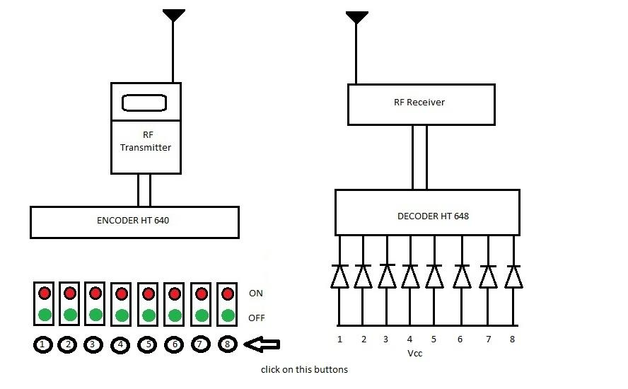

This circuit utilizes the RF module (Tx/Rx) for making a wireless remote, which could be used to drive an output from a distant place. RF module, as the name suggests, uses radio frequency to send signals. These signals are transmitted at a particular frequency and a baud rate. A receiver can receive these signals only if it is configured for that frequency. A eight channel encoder/decoder pair has also been used in this system. The input signals, at the transmitter side, are taken through eight switches while the outputs are monitored on a set of eight LEDs corresponding to each input switch. The circuit can be used for designing Remote Appliance Control system. The outputs from the receiver can drive corresponding relays connected to any household appliance.
Transmitter & receiver
DESCRIPTION
This radio frequency (RF) transmission system employs Amplitude Shift Keying (ASK) with transmitter/receiver (Tx/Rx) pair operating at 434MHz. The transmitter module takes serial input and transmits these signals through RF. The transmitted signals are received by the receiver module placed away from the source of transmission. The system allows one way communication between two nodes, namely, transmission and reception. The RF module has been used in conjunction with a set of eight channel encoder/decoder ICs. Here HT640 & HT648 have been used as encoder and decoder respectively. The encoder converts the parallel inputs (from the remote switches) into serial set of signals. These signals are serially transferred through RF to the reception point. The decoder is used after the RF receiver to decode the serial format and retrieve the original signals as outputs. These outputs can be observed on corresponding LEDs.
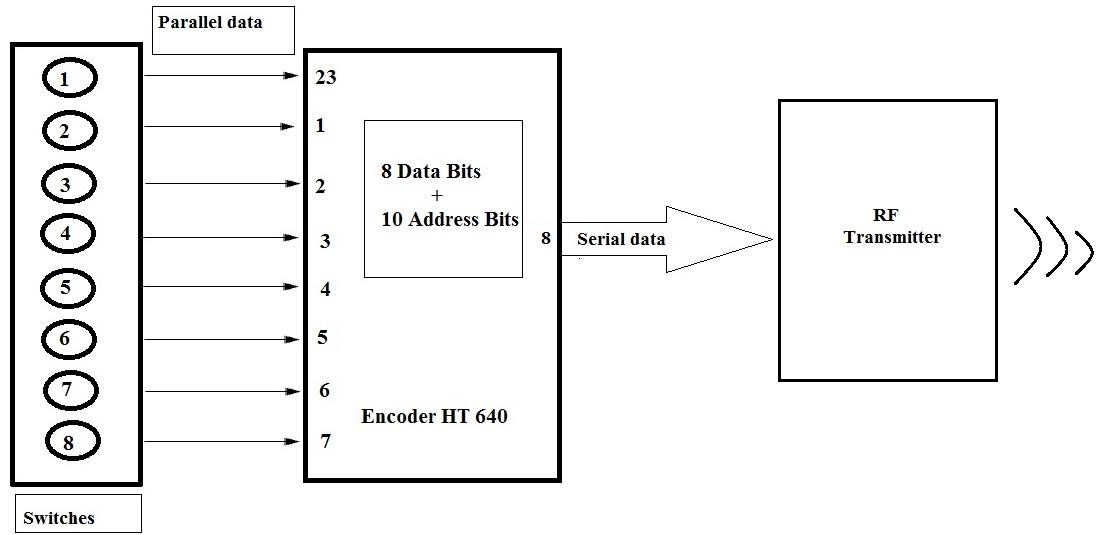
encoder module
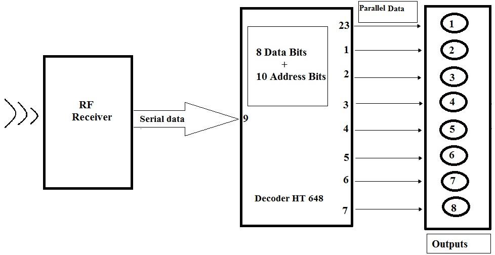
Transmitter, upon receiving serial data from encoder IC (HT640), transmits it wirelessly to the RF receiver. The receiver, upon receiving these signals, sends them to the decoder (HT648) through pin2. The serial data is received at the data pin (DIN, pin9) of HT648. The decoder then retrieves the original parallel format from the received serial data.
decoder module
COMPONENTS USED
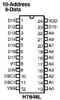
HT648 DECODER
HT648 IC comes from Holtek Company. HT648 is a decoder integrated circuit that belongs to 218 series of decoders. This series of decoders are mainly used for remote control system applications, like burglar alarm, car door controller, security system etc. It is mainly provided to interface RF and infrared circuits. They are paired with 218 series of encoders. The chosen pair of encoder/decoder should have same number of addresses and data format. In simple terms, HT648 converts the serial input into parallel outputs. It decodes the serial addresses and data received by, say, an RF receiver, into parallel data and sends them to output data pins. The serial input data is compared with the local addresses three times continuously. The input data code is decoded when no error or unmatched codes are found. A valid transmission in indicated by a high signal at VT pin. HT648 is capable of decoding 18 bits, of which 10 are address bits and 8 are data bits. The data on 8 bit latch type output pins emain unchanged until new is received.
HT640 ENCODER
HT640 is an encoder integrated circuit of 218 series of encoders. They are paired with 218 series of decoders for use in remote control system applications. It is mainly used in interfacing RF and infrared circuits. The chosen pair of encoder/decoder should have same number of addresses and data format. Simply put, HT640 converts the parallel inputs into serial output. It encodes the 18 bit parallel data into serial for transmission through an RF transmitter. These 18 bits are divided into 10 address bits and 8 data bits. HT640 has a transmission enable pin which is active high. When a trigger signal is received on TE pin, the programmed addresses/data are transmitted together with the header bits via an RF or an infrared transmission medium. HT640 begins a 8-word transmission cycle upon receipt of a transmission enable. This cycle is repeated as long as TE is kept high. As soon as TE returns to low, the encoder output completes its final cycle and then stops.
RF MODULES (434MHz)
RF Modules
The RF module, as the name suggests, operates at Radio Frequency. The corresponding frequency range varies between 30 kHz & 300 GHz. In this RF system, the digital data is represented as variations in the amplitude of carrier wave. This kind of modulation is known as Amplitude Shift Keying (ASK). Transmission through RF is better than IR (infrared) because of many reasons. Firstly, signals through RF can travel through larger distances making it suitable for long range applications. Also, while IR mostly operates in line-of-sight mode, RF signals can travel even when there is an obstruction between transmitter & receiver. Next, RF transmission is more strong and reliable than IR transmission. RF communication uses a specific frequency unlike IR signals which are affected by other IR emitting sources. This RF module comprises of an RF Transmitter and an RF Receiver. The transmitter/receiver (Tx/Rx) pair operates at a frequency of 434 MHz . An RF transmitter receives serial data and transmits it wirelessly through RF through its antenna connected at pin4. The transmission occurs at the rate of 1Kbps - 10Kbps.The transmitted data is received by an RF receiver operating at the same frequency as that of the transmitter. The RF module is often used along with a pair of encoder/decoder. The encoder is used for encoding parallel data for transmission feed while reception is decoded by a decoder. HT12E-HT12D, HT640-HT648, etc. are some commonly used encoder/decoder pair ICs.