A capacitor is a passive two-terminal electrical component that stores potential energy in an electric field. The effect of a capacitor is known as capacitance. While some capacitance exists between any two electrical conductors in proximity in a circuit, a capacitor is a component designed to add capacitance to a circuit. The capacitor was originally known as a condenser.
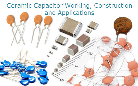
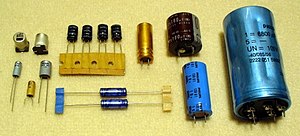
The physical form and construction of practical capacitors vary widely and many capacitor types are in common use. Most capacitors contain at least two electrical conductors often in the form of metallic plates or surfaces separated by a dielectric medium. A conductor may be a foil, thin film, sintered bead of metal, or an electrolyte. The nonconducting dielectric acts to increase the capacitor's charge capacity. Materials commonly used as dielectrics include glass, ceramic, plastic film, paper, mica, and oxide layers. Capacitors are widely used as parts of electrical circuits in many common electrical devices. Unlike a resistor, an ideal capacitor does not dissipate energy.


When two conductors experience a potential difference, for example, when a capacitor is attached across a battery, an electric field develops across the dielectric, causing a net positive charge to collect on one plate and net negative charge to collect on the other plate. No current actually flows through the dielectric, however, there is a flow of charge through the source circuit. If the condition is maintained sufficiently long, the current through the source circuit ceases. However, if a time-varying voltage is applied across the leads of the capacitor, the source experiences an ongoing current due to the charging and discharging cycles of the capacitor.
Capacitance is defined as the ratio of the electric charge on each conductor to the potential difference between them. The unit of capacitance in the International System of Units (SI) is the farad (F), defined as one coulomb per volt (1 C/V). Capacitance values of typical capacitors for use in general electronics range from about 1 picofarad (pF) (10−12 F) to about 1 millifarad (mF) (10−3 F).
The capacitance of a capacitor is proportional to the surface area of the plates (conductors) and inversely related to the gap between them. In practice, the dielectric between the plates passes a small amount of leakage current. It has an electric field strength limit, known as the breakdown voltage. The conductors and leads introduce an undesired inductanceand resistance.
Capacitors are widely used in electronic circuits for blocking direct current while allowing alternating current to pass. In analog filter networks, they smooth the output of power supplies. In resonant circuits they tune radios to particular frequencies. In electric power transmission systems, they stabilize voltage and power flow. The property of energy storage in capacitors was exploited as dynamic memory in early digital computers.
Electrolytic Capacitors
Aluminum electrolytic capacitors are polarized electrolytic capacitors whose anode electrode (+) is made of a pure aluminumfoil with an etched surface. The aluminum forms a very thin insulating layer of aluminium oxide by anodization that acts as the dielectric of the capacitor. A non-solid electrolyte covers the rough surface of the oxide layer, serving in principle as the second electrode (cathode) (-) of the capacitor. A second aluminum foil called “cathode foil” contacts the electrolyte and serves as the electrical connection to the negative terminal of the capacitor.
Aluminum electrolytic capacitors are divided into three subfamilies by the type of electrolyte:
- non-solid (liquid, wet) aluminum electrolytic capacitors,
- solid manganese dioxide aluminum electrolytic capacitors, and
- solid polymer aluminium electrolytic capacitors.
 Aluminum electrolytic capacitors with non-solid electrolyte are the most inexpensive type and also those with widest range of sizes, capacitance and voltage values. They are made with capacitance values from 0.1 µF up to 2,700,000 µF (2.7 F),[1] and rated voltages values from 4 V up to 630 V.[2] The liquid electrolyte provides oxygen for re-forming or self-healing of the dielectric oxide layer. However, it can evaporate through a temperature-dependent drying-out process, which causes electrical parameters to drift, limiting the service life time of the capacitors.
 Opened winding of a capacitor with multiple connected foils
 Closeup cross-section of an aluminum electrolytic capacitor design, showing capacitor anode foil with oxide layer, paper spacer soaked with electrolyte, and cathode foil

Construction of a typical single-ended aluminum electrolytic capacitor with non-solid electrolyte
Due to their relatively high capacitance values aluminum electrolytic capacitors have low impedance values even at lower frequencies like mains frequency. They are typically used in power supplies, switched-mode power supplies and DC-DC converters for smoothing and buffering rectified DC voltages in many electronic devices as well as in industrial power supplies and frequency converters as DC link capacitors for drives, inverters for photovoltaic, and converters in wind power plants. Special types are used for energy storage, for example in photoflash or strobe applications or for frequency coupling in audio applications.
Aluminum electrolytic capacitors are polarized capacitors because of their anodization principle. They can only be operated with DC voltage applied with the correct polarity. Operating the capacitor with wrong polarity or with AC voltage leads to a short circuit and can destroy the component. The exceptions is the bipolar aluminum electrolytic capacitor, which has a back-to-back configuration of two anodes in one case and can be used in AC applications.
Capacitors are widely used in electronic circuits for blocking direct current while allowing alternating current to pass. In analog filter networks, they smooth the output of power supplies. In resonant circuits they tune radios to particular frequencies. In electric power transmission systems, they stabilize voltage and power flow. The property of energy storage in capacitors was exploited as dynamic memory in early digital computers.
Electrolytic Capacitors
Aluminum electrolytic capacitors are polarized electrolytic capacitors whose anode electrode (+) is made of a pure aluminumfoil with an etched surface. The aluminum forms a very thin insulating layer of aluminium oxide by anodization that acts as the dielectric of the capacitor. A non-solid electrolyte covers the rough surface of the oxide layer, serving in principle as the second electrode (cathode) (-) of the capacitor. A second aluminum foil called “cathode foil” contacts the electrolyte and serves as the electrical connection to the negative terminal of the capacitor.
Aluminum electrolytic capacitors are divided into three subfamilies by the type of electrolyte:
- non-solid (liquid, wet) aluminum electrolytic capacitors,
- solid manganese dioxide aluminum electrolytic capacitors, and
- solid polymer aluminium electrolytic capacitors.
Aluminum electrolytic capacitors with non-solid electrolyte are the most inexpensive type and also those with widest range of sizes, capacitance and voltage values. They are made with capacitance values from 0.1 µF up to 2,700,000 µF (2.7 F),[1] and rated voltages values from 4 V up to 630 V.[2] The liquid electrolyte provides oxygen for re-forming or self-healing of the dielectric oxide layer. However, it can evaporate through a temperature-dependent drying-out process, which causes electrical parameters to drift, limiting the service life time of the capacitors.
Opened winding of a capacitor with multiple connected foils
Closeup cross-section of an aluminum electrolytic capacitor design, showing capacitor anode foil with oxide layer, paper spacer soaked with electrolyte, and cathode foil
Construction of a typical single-ended aluminum electrolytic capacitor with non-solid electrolyte
Due to their relatively high capacitance values aluminum electrolytic capacitors have low impedance values even at lower frequencies like mains frequency. They are typically used in power supplies, switched-mode power supplies and DC-DC converters for smoothing and buffering rectified DC voltages in many electronic devices as well as in industrial power supplies and frequency converters as DC link capacitors for drives, inverters for photovoltaic, and converters in wind power plants. Special types are used for energy storage, for example in photoflash or strobe applications or for frequency coupling in audio applications.
Aluminum electrolytic capacitors are polarized capacitors because of their anodization principle. They can only be operated with DC voltage applied with the correct polarity. Operating the capacitor with wrong polarity or with AC voltage leads to a short circuit and can destroy the component. The exceptions is the bipolar aluminum electrolytic capacitor, which has a back-to-back configuration of two anodes in one case and can be used in AC applications.
Anode
The basic material of the anode for aluminum electrolytic capacitors is a foil with a thickness of ~ 20–100 µm made of aluminum with a high purity of at least 99.99%.[7][11] This is etched (roughened) in an electrochemical process to increase the effective electrode surface.[12] By etching the surface of the anode, depending on the required rated voltage, the surface area can be increased by a factor of approximately 200 with respect to a smooth surface.[7]
After etching the aluminum anode the roughed surface is "anodic oxidized" or "formed". An electrically insulating oxide layer Al2O3 is thereby formed on the aluminum surface by application of a current in correct polarity if it is inserted in an electrolytic bath. This oxide layer is the capacitor dielectric.
This process of oxide formation is carried out in two reaction steps whereby the oxygen for this reaction has to come from the electrolyte.[13] First, a strongly exothermic reaction transforms the metallic aluminum (Al) into aluminum hydroxide, Al(OH)3:
- 2 Al + 6 H2O → 2 Al(OH)3 + 3 H2 ↑
This reaction is accelerated by a high electric field and high temperatures, and is accompanied by a pressure buildup in the capacitor housing caused by the released hydrogen gas. The gel-like aluminum hydroxide Al(OH)3, also called alumina trihydrate (ATH), is converted via a second reaction step (usually slowly over a few hours at room temperature, more rapidly in a few minutes at higher temperatures) into aluminum oxide, Al2O3:
- 2 Al(OH)3 → 2 AlO(OH) + 2 H2O → Al2O3 + 3 H2O
The aluminum oxide serves as dielectric and also protects the metallic aluminum against aggressive chemical reactions from the electrolyte. However, the converted layer of aluminum oxide is usually not homogeneous. It forms a complex multilayer structured laminate of amorphous, crystalline and porous crystalline aluminum oxide mostly covered with small residual parts of unconverted aluminum hydroxide. For this reason, in the formation of the anode foil, the oxide film is structured by a special chemical treatment so that either an amorphous oxide or a crystalline oxide is formed. The amorphous oxide variety yields higher mechanical and physical stability and fewer defects, thus increasing the long term stability and lowering the leakage current.
Amorphous oxide has a dielectric ratio of ~ 1.4 nm/V. Compared to crystalline aluminum oxide, which has a dielectric ratio of ~1.0 nm/V, the amorphous variety has a 40% lower capacitance at the same anode surface.[3] The disadvantage of crystalline oxide is its greater sensitivity to tensile stress, which may lead to microcracks when subjected to mechanical (winding) or thermal (soldering) stressors during the post-forming processes.
The various properties of oxide structures affect the subsequent characteristics of the electrolytic capacitors. Anode foils with amorphous oxide are primarily used for electrolytic capacitors with stable long-life characteristics, for capacitors with low leakage current values, and for e-caps with rated voltages up to about 100 volts. Capacitors with higher voltages, for example photoflash capacitors, usually containing anode foils with crystalline oxide.[14]
Because the thickness of the effective dielectric is proportional to the forming voltage, the dielectric thickness can be tailored to the rated voltage of the capacitor. For example, for low voltage types a 10 V electrolytic capacitor has a dielectric thickness of only about 0.014 µm, a 100 V electrolytic capacitor of only about 0.14 µm. Thus, the dielectric strength also influences the size of the capacitor. However, due to standardized safety margins the actual forming voltage of electrolytic capacitors is higher than the rated voltage of the component.
Aluminum anode foils are manufactured as so-called "mother rolls" of about 500 mm in width. They are pre-formed for the desired rated voltage and with the desired oxide layer structure. To produce the capacitors, the anode widths and lengths, as required for a capacitor, have to be cut from the mother roll.[15]


The basic material of the anode for aluminum electrolytic capacitors is a foil with a thickness of ~ 20–100 µm made of aluminum with a high purity of at least 99.99%.[7][11] This is etched (roughened) in an electrochemical process to increase the effective electrode surface.[12] By etching the surface of the anode, depending on the required rated voltage, the surface area can be increased by a factor of approximately 200 with respect to a smooth surface.[7]
After etching the aluminum anode the roughed surface is "anodic oxidized" or "formed". An electrically insulating oxide layer Al2O3 is thereby formed on the aluminum surface by application of a current in correct polarity if it is inserted in an electrolytic bath. This oxide layer is the capacitor dielectric.
This process of oxide formation is carried out in two reaction steps whereby the oxygen for this reaction has to come from the electrolyte.[13] First, a strongly exothermic reaction transforms the metallic aluminum (Al) into aluminum hydroxide, Al(OH)3:
- 2 Al + 6 H2O → 2 Al(OH)3 + 3 H2 ↑
This reaction is accelerated by a high electric field and high temperatures, and is accompanied by a pressure buildup in the capacitor housing caused by the released hydrogen gas. The gel-like aluminum hydroxide Al(OH)3, also called alumina trihydrate (ATH), is converted via a second reaction step (usually slowly over a few hours at room temperature, more rapidly in a few minutes at higher temperatures) into aluminum oxide, Al2O3:
- 2 Al(OH)3 → 2 AlO(OH) + 2 H2O → Al2O3 + 3 H2O
The aluminum oxide serves as dielectric and also protects the metallic aluminum against aggressive chemical reactions from the electrolyte. However, the converted layer of aluminum oxide is usually not homogeneous. It forms a complex multilayer structured laminate of amorphous, crystalline and porous crystalline aluminum oxide mostly covered with small residual parts of unconverted aluminum hydroxide. For this reason, in the formation of the anode foil, the oxide film is structured by a special chemical treatment so that either an amorphous oxide or a crystalline oxide is formed. The amorphous oxide variety yields higher mechanical and physical stability and fewer defects, thus increasing the long term stability and lowering the leakage current.

Amorphous oxide has a dielectric ratio of ~ 1.4 nm/V. Compared to crystalline aluminum oxide, which has a dielectric ratio of ~1.0 nm/V, the amorphous variety has a 40% lower capacitance at the same anode surface.[3] The disadvantage of crystalline oxide is its greater sensitivity to tensile stress, which may lead to microcracks when subjected to mechanical (winding) or thermal (soldering) stressors during the post-forming processes.
The various properties of oxide structures affect the subsequent characteristics of the electrolytic capacitors. Anode foils with amorphous oxide are primarily used for electrolytic capacitors with stable long-life characteristics, for capacitors with low leakage current values, and for e-caps with rated voltages up to about 100 volts. Capacitors with higher voltages, for example photoflash capacitors, usually containing anode foils with crystalline oxide.[14]
Because the thickness of the effective dielectric is proportional to the forming voltage, the dielectric thickness can be tailored to the rated voltage of the capacitor. For example, for low voltage types a 10 V electrolytic capacitor has a dielectric thickness of only about 0.014 µm, a 100 V electrolytic capacitor of only about 0.14 µm. Thus, the dielectric strength also influences the size of the capacitor. However, due to standardized safety margins the actual forming voltage of electrolytic capacitors is higher than the rated voltage of the component.
Aluminum anode foils are manufactured as so-called "mother rolls" of about 500 mm in width. They are pre-formed for the desired rated voltage and with the desired oxide layer structure. To produce the capacitors, the anode widths and lengths, as required for a capacitor, have to be cut from the mother roll.[15]
Cathode
The second aluminum foil in the electrolytic capacitor, called the "cathode foil", serves to make electrical contact with the electrolyte. This foil has a somewhat lower degree of purity, about 99.8%. It is always provided with a very thin oxide layer, which arises from the contact of the aluminum surface with the air in a natural way. In order to reduce the contact resistance to the electrolyte and to make it difficult for oxide formation during discharging, the cathode foil is alloyed with metals such as copper, silicon, or titanium. The cathode foil is also etched to enlarge the surface.
Because of the extremely thin oxide layer, which corresponds to a voltage proof of about 1.5 V, their specific capacitance is, however, much higher than that of anode foils.[7] To justify the need for a large surface capacitance of the cathode foil see the section on charge/discharge stability below.
The cathode foils, as the anode foils, are manufactured as so-called "mother rolls", from which widths and lengths are cut off, as required, for capacitor production.
Electrolyte
The electrolytic capacitor got its name from the electrolyte, the conductive liquid inside the capacitor. As a liquid it can be adapted to the porous structure of the anode and the grown oxide layer with the same shape and form as a "tailor-made" cathode. An electrolyte always consists of a mixture of solventsand additives to meet given requirements. The main electrical property of the electrolyte is its conductivity, which is physically an ion-conductivity in liquids. In addition to the good conductivity of operating electrolytes, various other requirements are, among other things, chemical stability, high flash point, chemical compatibility with aluminum, low viscosity, low environmental impact and low costs. The electrolyte should also provide oxygen for forming and self-healing processes, and all this within a temperature range as wide as possible. This diversity of requirements for the liquid electrolyte results in a wide variety of proprietary solutions.[16][17]
The electrolytic systems used today can be roughly summarized into three main groups:
- Electrolytes based on ethylene glycol and boric acid. In these so-called glycol or borax electrolyte an unwanted chemical crystal water reaction occurs according to the scheme: "acid + alcohol" gives "ester + water". These borax electrolytes are standard electrolytes, long in use, and with a water content between 5 and 20%. They work at a maximum temperature of 85 °C or 105 °C in the entire voltage range up to 600 V. Even with these capacitors, the aggressiveness of the water must be prevented by appropriate measures.[18]
- Almost anhydrous electrolytes based on organic solvents, such as dimethylformamide (DMF), dimethylacetamide (DMA), or γ-butyrolactone (GBL). These capacitors with organic solvent electrolytes are suitable for temperature ranges from 105 °C, 125 °C or 150 °C, have low leakage current values and have very good long-term capacitor behavior.
- Water based electrolytes with high water content, up to 70% water for so-called "low-impedance", "low-ESR" or "high-ripple-current" electrolytic capacitors with rated voltages up to 100 V[19] for low-cost mass-market applications. The aggressiveness of the water for aluminum must be prevented with suitable additives.[20]
Since the amount of liquid electrolyte during the operating time of the capacitors decreases over time through self-healing and by diffusion through the seal, the electrical parameters of the capacitors may be adversely affected, limiting the service life or lifetime of "wet" electrolytic capacitors, see the section on lifetime below.
Separator
The anode and cathode foils must be protected from direct contact with each other because such contact, even at relatively low voltages, may lead to a short circuit. In case of direct contact of both foils the oxide layer on the anode surface gives no protection. A spacer or separator made of a special highly absorbent paper with high purity protects the two metal foils from direct contact. This capacitor paper also serves as a reservoir for the electrolyte to extend the lifetime of the capacitor.
The thickness of the spacer depends on the rated voltage of the electrolytic capacitor. It is up to 100 V between 30 and 75 µm.[21] For higher voltages, several layers of paper (duplex paper) are used to increase the breakdown strength.
Encapsulation
The encapsulation of aluminum electrolytic capacitors is also made of aluminum in order to avoid galvanic reactions, normally with an aluminum case (can, tub). For radial electrolytic capacitors it is connected across the electrolyte with a non-defined resistance to the cathode (ground). For axial electrolytic capacitors, however, the housing is specifically designed with a direct contact to the cathode.
In case of a malfunction, overload or wrong polarity operating inside the electrolytic capacitor housing, substantial gas pressure can arise. The tubs are designed to open a pressure relief vent and release high pressure gas, including parts of the electrolyte. This vent protects against bursting, explosion or fly away of the metal tub.
For smaller housings the pressure relief vent is carved in the bottom or the notch of the tub. Larger capacitors like screw-terminal capacitors have a lockable overpressure vent and must be mounted in an upright position.
Sealing
The sealing materials of aluminum electrolytic capacitors depend on the different styles. For larger screw-terminal and snap-in capacitors the sealing washer is made of a plastic material. Axial electrolytic capacitors usually have a sealing washer made of phenolic resin laminated with a layer of rubber. Radial electrolytic capacitors use a rubber plug with a very dense structure. All sealing materials must be inert to the chemical parts of the electrolyte and may not contain soluble compounds that could lead to contamination of the electrolyte. To avoid leakage, the electrolyte must not be aggressive to the sealing material.
The sealing materials of aluminum electrolytic capacitors depend on the different styles. For larger screw-terminal and snap-in capacitors the sealing washer is made of a plastic material. Axial electrolytic capacitors usually have a sealing washer made of phenolic resin laminated with a layer of rubber. Radial electrolytic capacitors use a rubber plug with a very dense structure. All sealing materials must be inert to the chemical parts of the electrolyte and may not contain soluble compounds that could lead to contamination of the electrolyte. To avoid leakage, the electrolyte must not be aggressive to the sealing material.
Leakage current
A characteristic property of electrolytic capacitors is the "leakage current". This DC current is represented by the resistor Rleak in parallel with the capacitor in the series-equivalent circuit of electrolytic capacitors, and flows if a voltage is applied.
The leakage current includes all weak imperfections of the dielectric caused by unwanted chemical processes and mechanical damage and is the DC current that can pass through the dielectric after applying a voltage in correct polarity. It depends on the capacitance value, on applied voltage and temperature of the capacitor, on measuring time, on the kind of electrolyte, and on preconditions like previous storage time without voltage applied or thermic stress from soldering. (All non-solid electrolytic capacitors needs a recovery time of some hours after soldering before measuring the leakage current. Non-solid chip capacitors need a recovery time after reflow soldering of about 24 hours.) Leakage current is reduced by applying operational voltage by self-healing processes.
The leakage current drops in the first minutes after applying DC voltage. In this time the dielectric oxide layer can repair all weaknesses by building up new layers in a self-healing process. The time it takes leakage current to drop generally depends on the kind of electrolyte. Solid electrolytes' leakage current drops much faster than in the case of non-solid types, but it remain at a somewhat higher level. Wet electrolytic capacitors with high water contend electrolytes in the first minutes generally have higher leakage current than those with organic electrolyte, but after several minutes they reach the same level. Although the leakage current of electrolytic capacitors is higher compared with the current flow over the insulation resistance at ceramic or film capacitors, the self-discharge of modern non-solid electrolytic capacitors can take several weeks.
The leakage current Ileak specification in manufacturers' data sheets refers to the capacitor's capacitance value CR, rated voltage UR, a correlation factor and a minimum current value. For example,
After a measuring time of 2 or 5 minutes, depending on the data sheet specification, the measured leakage current value has to be lower than the calculated value. Normally the leakage current is always lower the longer the capacitor voltage is applied. The leakage current during operation after, for example, one hour is the operational leakage current. This value depends strongly on the manufacturer's series characteristics. It could be lower than 1/100 of the specified value.
The leakage current depends on the applied voltage and the ambient temperature. The value during continual operation at 85 °C is approximagtely four times higher than at 20 °C. Otherwise the value is approximately one half, reducing the applied voltage to 70% of the rated voltage.[41]
Non-solid aluminum electrolytic capacitors that leakage current after an operation time of, for example, one hour remain on a higher level than specified. Mostly they have been mechanically damaged internally due to high mechanical stress during mounting.


A characteristic property of electrolytic capacitors is the "leakage current". This DC current is represented by the resistor Rleak in parallel with the capacitor in the series-equivalent circuit of electrolytic capacitors, and flows if a voltage is applied.
The leakage current includes all weak imperfections of the dielectric caused by unwanted chemical processes and mechanical damage and is the DC current that can pass through the dielectric after applying a voltage in correct polarity. It depends on the capacitance value, on applied voltage and temperature of the capacitor, on measuring time, on the kind of electrolyte, and on preconditions like previous storage time without voltage applied or thermic stress from soldering. (All non-solid electrolytic capacitors needs a recovery time of some hours after soldering before measuring the leakage current. Non-solid chip capacitors need a recovery time after reflow soldering of about 24 hours.) Leakage current is reduced by applying operational voltage by self-healing processes.
The leakage current drops in the first minutes after applying DC voltage. In this time the dielectric oxide layer can repair all weaknesses by building up new layers in a self-healing process. The time it takes leakage current to drop generally depends on the kind of electrolyte. Solid electrolytes' leakage current drops much faster than in the case of non-solid types, but it remain at a somewhat higher level. Wet electrolytic capacitors with high water contend electrolytes in the first minutes generally have higher leakage current than those with organic electrolyte, but after several minutes they reach the same level. Although the leakage current of electrolytic capacitors is higher compared with the current flow over the insulation resistance at ceramic or film capacitors, the self-discharge of modern non-solid electrolytic capacitors can take several weeks.
The leakage current Ileak specification in manufacturers' data sheets refers to the capacitor's capacitance value CR, rated voltage UR, a correlation factor and a minimum current value. For example,

After a measuring time of 2 or 5 minutes, depending on the data sheet specification, the measured leakage current value has to be lower than the calculated value. Normally the leakage current is always lower the longer the capacitor voltage is applied. The leakage current during operation after, for example, one hour is the operational leakage current. This value depends strongly on the manufacturer's series characteristics. It could be lower than 1/100 of the specified value.
The leakage current depends on the applied voltage and the ambient temperature. The value during continual operation at 85 °C is approximagtely four times higher than at 20 °C. Otherwise the value is approximately one half, reducing the applied voltage to 70% of the rated voltage.[41]
Non-solid aluminum electrolytic capacitors that leakage current after an operation time of, for example, one hour remain on a higher level than specified. Mostly they have been mechanically damaged internally due to high mechanical stress during mounting.
Polarity marking
- Polarity marking for non-solid and solid aluminum electrolytic capacitors
-

-

- Aluminum electrolytic capacitors with non-solid electrolyte have a polarity marking at the cathode (minus) side
- Aluminum electrolytic capacitors with solid electrolyte have a polarity marking at the anode (plus) side
SMD style electrolytic capacitors with non-solid electrolyte (vertical-chips, V-chips) have a colored filled half circle or a minus bar on the top case side visible to indicate the minus terminal side. Additionally, the insulating plate under the capacitor body uses two skewed edges to indicate that the negative terminal is on the complement position.
Radial or single-ended electrolytic capacitor styles have a bar across the side of the capacitor to indicate the negative terminal side, and the negative terminal lead is shorter than the positive terminal lead.
Axial electrolytic capacitor styles have a bar across or around the case pointing to the negative lead end to indicate the negative terminal. The positive terminal of the capacitor is on the side of the sealing. The negative terminal lead is shorter than the positive terminal lead.
On a printed circuit board it is customary to indicate the correct orientation by using a square through-hole pad for the positive lead and a round pad for the negative one.
- Polarity marking for non-solid and solid aluminum electrolytic capacitors


- Aluminum electrolytic capacitors with non-solid electrolyte have a polarity marking at the cathode (minus) side
- Aluminum electrolytic capacitors with solid electrolyte have a polarity marking at the anode (plus) side

SMD style electrolytic capacitors with non-solid electrolyte (vertical-chips, V-chips) have a colored filled half circle or a minus bar on the top case side visible to indicate the minus terminal side. Additionally, the insulating plate under the capacitor body uses two skewed edges to indicate that the negative terminal is on the complement position.
Radial or single-ended electrolytic capacitor styles have a bar across the side of the capacitor to indicate the negative terminal side, and the negative terminal lead is shorter than the positive terminal lead.
Axial electrolytic capacitor styles have a bar across or around the case pointing to the negative lead end to indicate the negative terminal. The positive terminal of the capacitor is on the side of the sealing. The negative terminal lead is shorter than the positive terminal lead.
On a printed circuit board it is customary to indicate the correct orientation by using a square through-hole pad for the positive lead and a round pad for the negative one.