POWER SUPPLY
Power supply is a reference to a source of electrical power. A device or system that supplies electrical or other types of energy to an output load or group of loads is called a power supply unit or PSU. The term is most commonly applied to electrical energy supplies, less often to mechanical ones, and rarely to others
This power supply section is required to convert AC signal to DC signal and also to reduce the amplitude of the signal. The available voltage signal from the mains is 230V/50Hz which is an AC voltage, but the required is DC voltage(no frequency) with the amplitude of +5V and +12V for various applications.
In this section we have Transformer, Bridge rectifier, are connected serially and voltage regulators for +5V and +12V (7805 and 7812) via a capacitor (1000µF) in parallel are connected parallel as shown in the circuit diagram below. Each voltage regulator output is again is connected to the capacitors of values (100µF, 10µF, 1 µF, 0.1 µF) are connected parallel through which the corresponding output(+5V or +12V) are taken into consideration.

Circuit Explanation
- Transformer
A transformer is a device that transfers electrical energy from one circuit to another through inductively coupled electrical conductors. A changing current in the first circuit (the primary) creates a changing magnetic field; in turn, this magnetic field induces a changing voltage in the second circuit (the secondary). By adding a load to the secondary circuit, one can make current flow in the transformer, thus transferring energy from one circuit to the other.

The secondary induced voltage VS, of an ideal transformer, is scaled from the primary
VP by a factor equal to the ratio of the number of turns of wire in their respective windings:
VP by a factor equal to the ratio of the number of turns of wire in their respective windings:
Basic principle
The transformer is based on two principles: firstly, that an electric current can produce a magnetic field (electromagnetism) and secondly that a changing magnetic field within a coil of wire induces a voltage across the ends of the coil (electromagnetic induction). By changing the current in the primary coil, it changes the strength of its magnetic field; since the changing magnetic field extends into the secondary coil, a voltage is induced across the secondary.
A simplified transformer design is shown below. A current passing through the primary coil creates a magnetic field. The primary and secondary coils are wrapped around a core of very high magnetic permeability, such as iron; this ensures that most of the magnetic field lines produced by the primary current are within the iron and pass through the secondary coil as well as the primary coil.

Induction law
The voltage induced across the secondary coil may be calculated from Faraday's law of
induction, which states that:
induction, which states that:
Where VS is the instantaneous voltage, NS is the number of turns in the secondary coil and Φ equals the magnetic flux through one turn of the coil. If the turns of the coil are oriented perpendicular to the magnetic field lines, the flux is the product of the magnetic field strength B and the area A through which it cuts. The area is constant, being equal to the cross-sectional area of the transformer core, whereas the magnetic field varies with time according to the excitation of the primary. Since the same magnetic flux passes through both the primary and secondary coils in an ideal transformer, the instantaneous voltage across the primary winding equals
Taking the ratio of the two equations for VS and VP gives the basic equation for stepping up
or stepping down the voltage
or stepping down the voltage
Ideal power equation
If the secondary coil is attached to a load that allows current to flow, electrical power is transmitted from the primary circuit to the secondary circuit. Ideally, the transformer is perfectly efficient; all the incoming energy is transformed from the primary circuit to the magnetic field and into the secondary circuit. If this condition is met, the incoming electric power must equal the outgoing power.
Pincoming = IPVP = Poutgoing = ISVS
giving the ideal transformer equation

Pin-coming = IPVP = Pout-going = ISVS
giving the ideal transformer equation
If the voltage is increased (stepped up) (VS > VP), then the current is decreased (stepped down) (IS < IP) by the same factor. Transformers are efficient so this formula is a reasonable approximation.
If the voltage is increased (stepped up) (VS > VP), then the current is decreased (stepped down) (IS < IP) by the same factor. Transformers are efficient so this formula is a reasonable approximation.
The impedance in one circuit is transformed by the square of the turns ratio. For example, if an impedance ZS is attached across the terminals of the secondary coil, it appears to the primary circuit to have an impedance of
This relationship is reciprocal, so that the impedance ZP of the primary circuit appears to the secondary to be
Detailed operation
The simplified description above neglects several practical factors, in particular the primary current required to establish a magnetic field in the core, and the contribution to the field due to current in the secondary circuit.
Models of an ideal transformer typically assume a core of negligible reluctance with two windings of zero resistance. When a voltage is applied to the primary winding, a small current flows, driving flux around the magnetic circuit of the core. The current required to create the flux is termed the magnetizing current; since the ideal core has been assumed to have near-zero reluctance, the magnetizing current is negligible, although still required to create the magnetic field.
The changing magnetic field induces an electromotive force (EMF) across each winding. Since the ideal windings have no impedance, they have no associated voltage drop, and so the voltages VP and VS measured at the terminals of the transformer, are equal to the corresponding EMFs. The primary EMF, acting as it does in opposition to the primary voltage, is sometimes termed the "back EMF". This is due to Lenz's law which states that the induction of EMF would always be such that it will oppose development of any such change in magnetic field.
- Bridge Rectifier
A diode bridge or bridge rectifier is an arrangement of four diodes in a bridge configuration that provides the same polarity of output voltage for any polarity of input voltage. When used in its most common application, for conversion of alternating current (AC) input into direct current (DC) output, it is known as a bridge rectifier. A bridge rectifier provides full-wave rectification from a two-wire AC input, resulting in lower cost and weight as compared to a center-tapped transformer design, but has two diode drops rather than one, thus exhibiting reduced efficiency over a center-tapped design for the same output voltage.
Basic Operation
When the input connected at the left corner of the diamond is positive with respect to the one connected at the right hand corner, current flows to the right along the upper colored path to the output, and returns to the input supply via the lower one.

When the right hand corner is positive relative to the left hand corner, current flows along the upper colored path and returns to the supply via the lower colored path.

In each case, the upper right output remains positive with respect to the lower right one. Since this is true whether the input is AC or DC, this circuit not only produces DC power when supplied with AC power: it also can provide what is sometimes called "reverse polarity protection". That is, it permits normal functioning when batteries are installed backwards or DC input-power supply wiring "has its wires crossed" (and protects the circuitry it powers against damage that might occur without this circuit in place).
Prior to availability of integrated electronics, such a bridge rectifier was always constructed from discrete components. Since about 1950, a single four-terminal component containing the four diodes connected in the bridge configuration became a standard commercial component and is now available with various voltage and current ratings.

Output smoothing (Using Capacitor)
For many applications, especially with single phase AC where the full-wave bridge serves to convert an AC input into a DC output, the addition of a capacitor may be important because the bridge alone supplies an output voltage of fixed polarity but pulsating magnitude (see diagram above).

The function of this capacitor, known as a reservoir capacitor (aka smoothing capacitor) is to lessen the variation in (or 'smooth') the rectified AC output voltage waveform from the bridge. One explanation of 'smoothing' is that the capacitor provides a low impedance path to the AC component of the output, reducing the AC voltage across, and AC current through, the resistive load. In less technical terms, any drop in the output voltage and current of the bridge tends to be cancelled by loss of charge in the capacitor.
This charge flows out as additional current through the load. Thus the change of load current and voltage is reduced relative to what would occur without the capacitor. Increases of voltage correspondingly store excess charge in the capacitor, thus moderating the change in output voltage / current. Also see rectifier output smoothing.
The simplified circuit shown has a well deserved reputation for being dangerous, because, in some applications, the capacitor can retain a lethal charge after the AC power source is removed. If supplying a dangerous voltage, a practical circuit should include a reliable way to safely discharge the capacitor. If the normal load can not be guaranteed to perform this function, perhaps because it can be disconnected, the circuit should include a bleeder resistor connected as close as practical across the capacitor. This resistor should consume a current large enough to discharge the capacitor in a reasonable time, but small enough to avoid unnecessary power waste.
Because a bleeder sets a minimum current drain, the regulation of the circuit, defined as percentage voltage change from minimum to maximum load, is improved. However in many cases the improvement is of insignificant magnitude.
The capacitor and the load resistance have a typical time constant τ = RC where C and R are the capacitance and load resistance respectively. As long as the load resistor is large enough so that this time constant is much longer than the time of one ripple cycle, the above configuration will produce a smoothed DC voltage across the load.
In some designs, a series resistor at the load side of the capacitor is added. The smoothing can then be improved by adding additional stages of capacitor–resistor pairs, often done only for sub-supplies to critical high-gain circuits that tend to be sensitive to supply voltage noise.
The idealized waveforms shown above are seen for both voltage and current when the load on the bridge is resistive. When the load includes a smoothing capacitor, both the voltage and the current waveforms will be greatly changed. While the voltage is smoothed, as described above, current will flow through the bridge only during the time when the input voltage is greater than the capacitor voltage. For example, if the load draws an average current of n Amps, and the diodes conduct for 10% of the time, the average diode current during conduction must be 10n Amps. This non-sinusoidal current leads to harmonic distortion and a poor power factor in the AC supply.
In a practical circuit, when a capacitor is directly connected to the output of a bridge, the bridge diodes must be sized to withstand the current surge that occurs when the power is turned on at the peak of the AC voltage and the capacitor is fully discharged. Sometimes a small series resistor is included before the capacitor to limit this current, though in most applications the power supply transformer's resistance is already sufficient.
Output can also be smoothed using a choke and second capacitor. The choke tends to keep the current (rather than the voltage) more constant. Due to the relatively high cost of an effective choke compared to a resistor and capacitor this is not employed in modern equipment.
Some early console radios created the speaker's constant field with the current from the high voltage ("B +") power supply, which was then routed to the consuming circuits, (permanent magnets were considered too weak for good performance) to create the speaker's constant magnetic field. The speaker field coil thus performed 2 jobs in one: it acted as a choke, filtering the power supply, and it produced the magnetic field to operate the speaker.
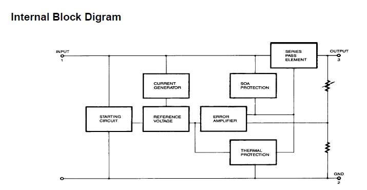
- Voltage Regulator
A voltage regulator is an electrical regulator designed to automatically maintain a constant voltage level.
The 78xx (also sometimes known as LM78xx) series of devices is a family of self-contained fixed linear voltage regulator integrated circuits. The 78xx family is a very popular choice for many electronic circuits which require a regulated power supply, due to their ease of use and relative cheapness. When specifying individual ICs within this family, the xx is replaced with a two-digit number, which indicates the output voltage the particular device is designed to provide (for example, the 7805 has a 5 volt output, while the 7812 produces 12 volts). The 78xx line is positive voltage regulators, meaning that they are designed to produce a voltage that is positive relative to a common ground. There is a related line of 79xx devices which are complementary negative voltage regulators. 78xx and 79xx ICs can be used in combination to provide both positive and negative supply voltages in the same circuit, if necessary.
78xx ICs have three terminals and are most commonly found in the TO220 form factor, although smaller surface-mount and larger TrO3 packages are also available from some manufacturers. These devices typically support an input voltage which can be anywhere from a couple of volts over the intended output voltage, up to a maximum of 35 or 40 volts, and can typically provide up to around 1 or 1.5 amps of current (though smaller or larger packages may have a lower or higher current rating).